A current sensor module is an electronic device that detects and measures the flowing electric current throughout a conductor and changes it into a current, voltage, or digital signal. So the applications of these modules involve digital watt meters, switching mode power supplies, battery chargers, over-current protection circuits, programmable current sources, etc. Thus, the examples of current sensor modules are; ACS712, INA219¸ ACS758, WCS1800, LCB-050B, etc. This article elaborates on an INA219 current sensor module, pinout, features, specifications, and applications.
What is the INA219 Current Sensor Module?
The INA219 is a small and powerful DC sensor module introduced by TI (Texas Instruments). It is a Bidirectional, zero-drift, Power Monitor module that monitors bus voltage, shunt voltage, current, and power. So this module uses an integrated interface for communication with different microcontrollers and is well-matched with SMBus and I2C. It has an ADC with 12-bit and 16 programmable high-resolution addresses for flexible configuration.
INA219 module is available with an extra multiplier register that changes the power supply to watts. So this module can be utilized in different applications like power management test equipment, and over current protection within servers, battery chargers & any system that needs a low-cost and high-accuracy technique used for monitoring current & power.
Working
The INA219 DC sensor module works by sensing current, shunt voltage, and power and submitting the data through the I2C protocol. So this module has 0.1 Ohms, a 1% shunt resistor which fulfills the necessities of current measurements. So it has a 12-bit powerful ADC that changes the detected current through a precision amplifier. Thus, the current sensing range will be ±3.2A with a 0.8mA resolution. So this current sensor module measures up to +26V DC voltage.
The INA219 module measures current using Ohm’s law through a resistor & measures the voltage drop across it. So the resistor is known as a shunt which is 0.1 ohms. So to measure the current, the voltage drop is multiplied by 10 across the shunt.
The INA219 can also measure the voltage drop across the bus between VIN & GND. So it utilizes the voltage drop across the shunt & the voltage drop across the bus to measure the power consumption of the consumer.
The INA219 utilizes a 12-bit ADC to change the sensed current through a precision amplifier. After that, it submits the information to a host microcontroller with the I2C bus protocol. So this module has a programmable calibration value which is merged through an internal multiplier and it allows for direct current readouts within amperes.
Pin Configuration:
The pin configuration of the INA219 module is shown below. This module includes 8 pins which are discussed below.
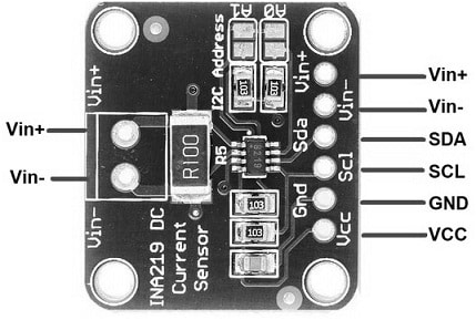
INA219 Module Pin Configuration
- Pin-1 (A1): It is an address-1 pin of the current sensor module.
- Pin-2 (A0): It is an address-0 pin of the module.
- Pin-3 (SDA): It is a serial data pin of the module that is utilized for the data line of the I2C interface.
- Pin-4 (SCL): It is a serial CLK pin of the module, which is used for the CLK line of the I2C interface.
- Pin-5 (VCC): It is a power supply pin of the module that can handle 3.3V to 5.5V input voltage.
- Pin-6 (GND): It is a Ground pin.
- Pin-7 (IN–): It is a negative analog i/p pin that connects to the -ve terminal of the supply voltage that you desire to measure.
- Pin-8 (IN+): It is a positive analog i/p pin that connects to the +ve terminal of the supply voltage that you desire to measure.
Features & Specifications:
The features and specifications of the INA219 current sensor module include the following.
- INA219 is a DC sensor module.
- This module is available in SOT23-8 & SOIC-8 packages.
- This module includes calibration registers to decrease insecurity in the voltage, current, and power values.
- It includes 16 programmable addresses & filtering options.
- This sensor module can also be available in two grades like; INA219A & INA219B.
- Its operational voltage ranges from 3 to 5.5 Volts
- Operating temperature ranges from -400C to – 1250C.
- Its bus voltage ranges from 0 to 26 Volts.
- The current sensing range is ±3.2A with ±0.8mAmps resolution.
INA219 Current Sensor Module Components
The INA219 current sensor module includes different components like a current sensing resistor, INA219 IC, and I2C Interface which are discussed below.
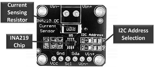
INA219 Module Components
- The current sensing resistor in this module measures voltage (V), current (I) & power (P) by measuring the drop of voltage across it. So it can be changed as per the requirement.
- The INA219 integrated circuit processes all the signal & data.
- The I2C interface bus in this module has SCL & SDA, thus these are used to communicate data between the sensor module & the microcontroller.
Equivalents & Alternatives :
The equivalent INA219 current sensor module is ACS712 and INA3221. So alternative current sensor modules are; CJMCU-219, ACS758, CJMCU-219, LCB-050B, WCS1800, etc.
I2C Address
The INA219 module utilizes the I2C protocol to communicate with different microcontrollers, where every device on the I2C bus should include a unique address. So the default I2C address for this module is 0x40 (or) 1000000 in binary.
If you want to utilize various INA219 sensors on a similar I2C bus then the address can be adjusted. So this module allows up to sixteen different I2C addresses which range from 0x40 addresses to 0x4F. This can be attained by arranging the two address pins states like A0 & A1. These two pins on the sensor module are frequently found with jumpers or solder pads. Thus these are connected to the GND by default which communicates to the 0x40 default address.
Here the I2C address can be changed by modifying the connections of these pins to either SDA, GND, SCL, or not connected. If the A0 pin is connected to SDA and the A1 pin to the GND pin, then the address will be 0x48.
Thus, if you want to comprise numerous INA219 modules within a similar system, then a unique address needs to be set for each one by arranging the pins A0 & A1 accordingly. So if you want to modify the I2C address, then you should update the address within the software of your microcontroller thus it knows wherever to find every INA219 module on the I2C bus.
Register Address Values Calculations
The INA219 module includes a set of internal registers that hold measurement data as well as control settings. So they can be accessed through the I2C interface to arrange the IC, start measurements & read measurement results.
Configuration Register:
This register address is 00h which is used for controlling various aspects of the module like the PGA gain, bus voltage range, ADC resolution or averaging, operating mode, etc. So it can be read (or) written to arrange the IC as required.
Shunt Voltage Register:
This register address is 01h which holds the raw measurement outcome for the shunt voltage. So it can be read to get the measurement of shunt voltage, and the value should be processed to obtain the actual voltage within volts. Thus, shunt voltage can be measured by using the raw reading with the shunt voltage register & multiplying it by 10 µV. So this formula can be written as;
Shunt Voltage = Shunt Voltage Register Value x 10 µV.
Bus Voltage Register:
This register’s address value 02h holds the result of raw measurement mainly for the bus voltage. So it can be read to get the measurement of bus voltage & this value should be processed to acquire the actual voltage within volts.
Thus, bus voltage can be measured by taking the raw reading using the bus voltage register & multiplying it with 4 mV. So its formula can be written as;
Bus Voltage = bus voltage register value x 4 mV
Power Register:
This register address value 03h holds the measured power value. So it can be read to acquire the power measurement & its value should be processed to acquire the actual power within watts. The power can be measured in watts by using the raw reading with the power register & it can be multiplied by the Power_LSB value. So this can be measured by the following formula.
Power = Power Register Value x Power_LSB
Current Register:
This address value 04h of this register has the measured current value. So it can be read to get the current measurement & its value should be processed to acquire the actual current within amperes.
Thus current can be measured by using the raw reading with the current register and it can be multiplied by the Current_LSB value. So the formula used to measure this value is given as;
Current = Current Register Value x Current_LSB
INA219 Current Sensor Module with Arduino Board
The INA219 current sensor module interfacing with the Arduino board is shown below. So this interfacing is straightforward with an Arduino, power supply, and external load. Thus the connections of this interfacing follow as;
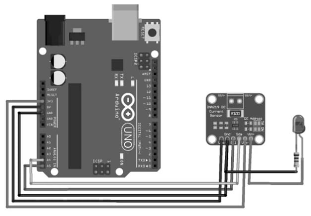
INA219 Current Sensor Module with Arduino Board
- The VCC pin of the INA219 current sensor module is connected to the 5V pin of the Arduino board.
- The GND pin of the INA219 current sensor module is connected to the GND pin of the Arduino board.
- The SCL pin of the INA219 current sensor module is connected to the A5 (SCL) pin of the Arduino board.
- The SDA pin of the INA219 current sensor module is connected to the A4 (SDA) pin of the Arduino board.
- The Vin+ (positive terminal) of the INA219 current sensor module is connected to the power source pin of the Arduino board.
- The Vin- (load) of the INA219 current sensor module is connected to the load pin of the Arduino board.
Code
The required code for the INA219 current sensor module with Arduino board is shown below.
#include <Wire.h>
#include <Adafruit_INA219.h>
Adafruit_INA219 ina219;
void setup()
{
Serial.begin(9600);
if (!ina219.begin()) {
Serial.println(“INA219 not found”); // Print error message if INA219 is not found
while (1) {
delay(10);
}
}
// To use a slightly lower 32V, 1A range (higher precision on amps):
//ina219.setCalibration_32V_1A();
// Or to use a lower 16V, 400mA range (higher precision on volts and amps):
ina219.setCalibration_16V_400mA(); // Set calibration for INA219
}
void loop()
{
float shuntVoltage = 0;
float busVoltage = 0;
current_mA = 0;
loadVoltage = 0;
power_mW = 0;
shuntVoltage = ina219.getShuntVoltage_mV(); // Read shunt voltage
busVoltage = ina219.getBusVoltage_V(); // Read bus voltage
current_mA = ina219.getCurrent_mA(); // Read current
power_mW = ina219.getPower_mW(); // Read power
loadVoltage = busVoltage + (shuntVoltage / 1000); // Calculate load voltage
Serial.print(“Bus Voltage: “);
Serial.print(busVoltage);
Serial.println(” V”);
Serial.print(“Shunt Voltage: “);
Serial.print(shuntVoltage);
Serial.println(” mV”);
Serial.print(“Load Voltage: “);
Serial.print(loadVoltage);
Serial.println(” V”);
Serial.print(“Current: “);
Serial.print(current_mA);
Serial.println(” mA”);
Serial.print(“Power: “);
Serial.print(power_mW);
Serial.println(” mW”);
Serial.println(“”);
delay(2000); // Delay for 2 seconds
}
Working
The above sample code demonstrates how to interface the INA219 module with the Arduino board. So this code can be compiled by downloading and adding the Adafruit INA219 library to the folder of your Arduino library. Once the program is uploaded to your Arduino board, open the serial monitor and set the baud rate to 9600. So if the code works properly, then output within the serial monitor which displays measured values like shunt voltage, bus voltage, current, load voltage, and power at normal intervals.
Difference between INA219 and INA260
The difference between INA219 and INA260 sensors includes the following.
|
INA219 |
INA260 |
| The INA219 module is a current shunt & power monitor that senses voltage, current, & power. | The INA260 module is a digital voltage, current, and power monitor so that measures current &power with high precision. |
| It is available in SOT23-8 & SOIC-8 Packages. | It is available in the 16-pin TSSOP package. |
| This module utilizes an exterior current-sense resistor. | It has one in-built resistor.
|
| This module senses shunts on buses that vary from 0V to 26V. | INA260 module measures up to +36V at equal to 15Amps continuous. |
| It has two grades A & B where the B grade has high accuracy & precision specifications. | This module has calibration-equivalent measurement precision with very low-temperature drift performance. |
| The INA219 module is compatible with an I2C (or) SMBUS with 16 programmable addresses. | It is compatible with an I2C & SMBus interface. |
| It operates with a single 3V to 5.5V supply and it draws 1mA of maximum current supply. | This module operates from 2.7 to 5.5 V which draws 310μA of current supply. |
| It has a programmable calibration value that allows for direct current readouts in amperes. | This module supports current measurements in any direction. |
| It has two measurement modes continuous & on-demand. | The INA260 has three measurement modes continuous, triggered, and shutdown. |
Advantages & Disadvantages
The advantages of the INA219 current sensor module include the following.
- INA219 is a small with the highest precision current sensor module.
- This module solves all your power-monitoring issues.
- This module has an SMBUS or I2C compatible interface including 16 programmable addresses.
- This sensor module can communicate with different microcontrollers like ESP, Raspberry Pi, Arduino, etc.
- This module reliably detects a few milliamperes currents.
- It includes a programmable calibration value & internal multiplier, thus it permits for DC readouts within amperes.
- It monitors both bus supply voltage and shunt voltage drop.
- This module can also have a multiplying register, so it measures power in watts.
- It can average up to 128 samples to decrease noise.
- It uses a 3V to 5.5V single supply.
- This module is available in two grades A & B where the B grade module has high accuracy.
The disadvantages of the INA219 current sensor module include the following.
- The main drawback of this sensor is the intrinsic electrical connection, so it exists between the current to be calculated & the sensing circuit.
- Electrical isolation can be attained by using an isolation amplifier, thus it increases the price of the sensor.
- It is very difficult to adapt to the LabVIEW setting due to the lack of a current sensor library.
- This module sensor has around 2.3% absolute voltage inaccuracy at full scale.
INA219 Current Sensor Module Applications
The applications of the INA219 current sensor module include the following.
- INA219 is a zero drift current and power sensing bi-directional module, thus used in power profilers and digital multimeters.
- The INA219 module can be used in different applications like over-current protection within servers, power management, test equipment, battery chargers, etc.
- It is used in any system that needs a low-cost and high-accuracy technique for monitoring current & power.
- It is used in loggers, battery chargers, servers, notebook computers, telecom equipment, welding equipment, test equipment, power supplies, etc.
- This module monitors the circuit’s digital power thus it can also detect low and high voltage.
- This module is used to monitor & log load current.
Please refer to this link for the INA219 Current Sensor Module Datasheet.
Thus, this is an overview of the INA219 current sensor module. This current sensor measures from 10mA to 3A current values with a 0.76% average error. So it can also measure voltage values which range from 0Volt to 26Volts. Thus this sensor’s linearity test value R is 0.98 for voltage and current. This is a very famous power monitoring chip that is easy to employ within DIY projects. So, it measures up to +26VDC high side current although it is powered through 3V or 5V. Whenever this module is utilized with Arduino board then it has strong open-source library support which allows for plug-n-play functionality. So, here is a question for you, what is the ACS712 module?