An inductor is normally a coil of wire. When current is passing through that coil, the electric field will be generated. So the field will get induced. The induced filed depends on the number of turns and this is inductance. An inductor due to its inductance resists the flow of alternating current. Basing on the Lenz’s law inductor will resist change in current. Reactance is defined as the resistance offered to the AC currents by capacitors and inductors only. Usually, reactance is denoted by X, the frequency with f, Inductance with L, and capacitance with C. The inductive reactance is dependent on frequency. The calculation of this can be done using simple formulas.
What is an Inductive Reactance?
Inductive reactance is defined as the effect by which the current flow of an alternating current in an inductor is reduced. Any alternating current or changing current will get impeded due to the result of inductance associated with it.
Chokes and inductors are basically loops of wire or coils that are wound around some ferromagnetic material or around a hollow tube former for increasing their inductive value called inductance. When voltage is applied across terminals of an inductor, the Inductors store energy in the form of the magnetic field. For an inductor coil back emf voltage is proportional to the rate of change of current that is flowing through this.
Inductive Reactance
If we started examining or observing the self-inductance and the effects caused in the circuit then we can easily know the reason for this inductive reactance. To define this in a simple form it’s like opposition to the current flow.
When an inductor is applied with AC voltage, the flow of current will be different comparatively when it is applied with DC voltage. The phase difference between voltage and current waveforms will get produced by the sinusoidal supply. Both the frequency of the waveform and the inductance of the coil determine the opposition of current flow in the coil windings in the AC circuit.
AC resistance determines the opposition of current flow through coil in the AC circuit and it is commonly known as impedance (Z) of the circuit. For distinguishing DC resistance from AC resistance, the resistance always associates with DC circuits and the general term used for this is reactance. Reactance value is measured in ohms, just like resistance. To know the difference between the reactive value from resistive value, the reactance value is denoted by ‘X’.
As we are focusing on the component inductor, the reactance of an inductor is called inductive reactance. To simplify it in another form, it can be defined as the electric resistance of inductor when used in an AC circuit. The symbol for inductive reactance is XL.
Inductive Reactance Formula
The inductive reactance can be calculated by using the following formula. Inductive reactance is the product of 2 times pi and the inductance of the coil and the frequency of the AC current. So formula can be denoted as
XL= 2πfL
Where ‘XL’ is inductive reactance that is measured in ohms
f is the ‘AC’ frequency of the electrical supply in hertz
‘L’ is the inductance value of the coil in henries.
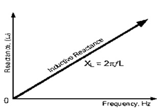
From this inductive reactance formula, we can clearly know that inductive reactance will increase when there is an increase in frequency or inductance. Inductive reactance will reach infinity when frequency approaches infinity and it acts as an open circuit. Similarly, it will approach zero when frequency decreases to zero and it acts as a short circuit. it clearly defines that frequency and inductive reactance are directly proportional.
Perfect inductor refers to that which has only inductance but no resistance and no capacitance. Although perfect inductors do not exist. To determine the formulas and calculations once we imagine the placement of a perfect inductor. If sine wave is applied to the perfect inductor, reactance impedes the flow of current and follow ohms law
XL =V/I
‘XL’ is inductive reactance in ohms
‘I’ is current in amps
‘V’ is the voltage in volts
In inductive reactance against frequency, as we clearly know that frequency is directly proportional to frequency. Therefore we can see that inductor has zero reactance at DC and the inductor has infinite reactance at high frequencies.
Inductive Reactance Formula Derivation
Sinusoidal alternating
Voltage V = Vmsinwt
Back emf induce, e =Ldi/dt
e=v
Ldi/dt=Vmsinwt
Di=Vm/l sinwtdt
Integration on both sides
∫ di= ∫Vm/L sinwtdt
I= Vm/wL sin (wt-π/2)
At wt=π sin (wt-π/2) =1
Im =Vm/wL
Vm/Im =wL
W=2πf
Inductive reactance XL =Vm/Im =2πfL
AC Supply through LR Series Circuit
Mostly we consider purely inductive coil, but every time considering a pure inductive coil will not be possible but solenoids will have a certain resistance, it doesn’t matter how much small it was associated with the coils turns of wire that is being used. So that we can consider this simple coil as it is being resistance in series with inductance.
Resistance ‘R’ and inductance ‘L’ are present in the AC circuit and the voltage V will be the phasor sum of VL and VR. The phase angle of the circuit is defined by the new phase angle between the current and the voltage and it is given by the Greek symbol phi.
Vector Diagram of Resultant Voltage
Here line OB is the horizontal current reference, OA is the voltage across the resistive component and it is in phase with current, OC represents inductive voltage that is 90 degrees in front of current, OD will give resulting supply voltage.
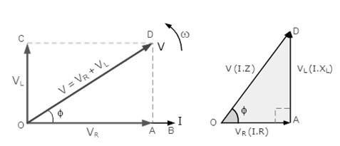
Vector Diagram of Resultant Voltage
V = RMS value of applied voltage
I = RMS value of the series current
VR = IR voltage drop across resistance which is in phase with the current
VL = voltage drop across inductance which leads current by 90 degrees
Phase Angle
When two or more inductive coils are connected in the series otherwise single coil when connected in series with many non-inductive resistances, resistive elements total resistance will be equal to R1+R2+R3, etc. it will give a total resistive value for the circuit.
Phase Angle
Coming to reactance, inductive elements total reactance is equal to X1+X2+X3, etc, and gives total reactance value of the circuit.
The difference between inductance and reactance includes
- Reactance is the effect of the inductance at a given frequency.
- Inductance is defined as a physical property of the conductor or coil. Units are henries and it doesn’t depend on the frequency of the signal in the component
- Coming to reactance, it is dependent on the frequency of the signal.
Please refer to this link to know more about Ohms law MCQs.
This is the complete description of inductive reactance, its formula, unit, and dimensions. Here is a question, what is the difference between reactance and capacitance.