RVDT full form is a Rotary Variable Differential Transformer, which is used to measure the angular displacement of the test circuit. It plays a significant role in the field of aircraft (to measure the aircraft throttle and flap control systems), aerospace, medical field to measure or vary the angular displacement and stabilize the system. The operation principle is similar to that of LVDT, wherein the cam-shaped core rotates between the winding with the help of shaft. In this article, a brief overview of the what is RVDT sensor is explained, it’s full form, working theory along with case study and experiments, advantages, disadvantages, and applications in real-time.
Construction
The below figure shows the typical module of RVDT.
The circuit diagram of RVDT, as shown in the below figure consists of one primary and two secondary winding. The physical parameters of the RVDT core and design aspects are selected in such a way that the coil generates angular displacement linearly with respect to the induced mutual inductance between the primary and individual secondary coils. It is also called a passive transducer since it is powered from an external electrical source and converts angular displacement into electrical signals. The other names for RVDT include an angular position sensor, differential transducer, RVDT transducer, inductive sensor (due to the absence of electronic circuits inside it). Its brushless continuous rotation property increases the reliability and durability of the system.
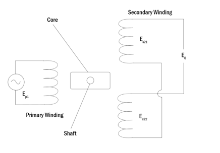
circuit-diagram-of-rotary-variable-differential-transformer
RVDT Mechanism
Let us assume that the secondary voltage of the RVDT transformer is Es21 and Es22, respectively.
The parameter ‘G’ denotes the RVDT Sensitivity
Theta (ϴ) defines the angular displacement of the shaft and is given by,
θ=G*(Es21-Es22)/(Es21-Es22))——(1)
The secondary voltage is calculated with the equation
Es22=Es22±G*θ——(2)
The differential output voltage across the secondary side is given by,
∆Es22=2*G*θ——(3)
RVDT working theory – (principle)
As mentioned in the earlier sections, the working principle of RVDT is similar to LVDT and operates on the principle of mutual induction. When the RVDT primary windings are subjected to an AC excitation voltage of around 5-15V and a frequency range of 50-400Hz, a magnetic field is induced inside the core. The secondary winding generates a magnetic current proportional to the induced magnetic field. The net RVDT output voltage is the difference between the induced voltage across secondary windings.
In general, the output voltage E_o is equal to,
Eo=Es21-Es22——(4)
With respect to the inner core position, the operating principle of RVDT is divided into three cases, and rvdt experiment is carried out on the same.
Case 1: When the core is precisely placed at null position (equilibrium state)
In this situation, the core is placed precisely at the center position of two secondary windings. The flux linkage between secondary windings ( S21and S22) is equal, and the net induced EMF is zero (Eo=Es21-Es22=0). There is no displacement in the core and also considered as a standard baseline value to measure the angular variations.
Case 2: Core rotation in a clockwise direction
In this condition, RVDT primary coil is connected to an external power source, and an EMF is induced inside the circuit. The core starts to rotate in a clockwise direction because of the flux linkage across
S21 is higher than S22. This in-turn signifies that EMF developed in S21is higher than S22. Hence S21>S21and the total differential voltage will be positive Es21-Es22= +ve. The primary voltage and the output voltage are in phase.
Case 3: Core rotation in an anti-clockwise direction
EMF is induced inside the RVDT circuit. The core starts to rotate in an anti-clockwise direction due to the fact that the flux linkage across S22is greater than S21. This in-turn signifies that EMF developed in S22 is higher than S21. Hence Es22>Es21and the total differential voltage will be negative Es22-Es21= -ve . The primary voltage and the output voltage are in 180 degrees out of phase (phase opposition).
Advantages
The advantages of Rotary Variable Differential Transformer are as follows
In comparison to other types, the accuracy of RVDT is limited, but notably more advantageous over different types of position measurement sensors.
1). Robust, durable, and suitable to extreme hard operating conditions
RVDT is robust in nature with higher product life. It can be reused to a greater number of operating conditions. Measure the angular displacements in even critical and ruff wear and tear applications. It is capable of withstanding extreme conditions such as high vibrations, overload, and shocks.
2). Cost-effective
If you are planning to minimize the measurement cost, then this is the go-to more top priority option. Cost occupies the major part of the project, especially if it was a limited budget. Along with robustness, the cost of RVDT is minimal compared to other sensors.
3). Reduced Maintenance and Easy to Manage
The construction of RVDT is simpler, with a reduced number of electronic components. The requirement of complicated circuits or specialty auxiliary parts to achieve angular throughput can be eradicated. With minimal parts, it also brings down the maintenance cost to a larger extent.
4). Compact in size
Reduced number of electronic components in RVDT scales down the overall size of the device to a relatively small area. A small space to fit the sensor is enough to interface with the external devices. This factor can also increase the number of applications.
5). Contactless construction
Since there is no mechanical contact between the devices, RVDT hinders the performance issues related to functional integrity and generation of friction due to wear and tear inside the system.
Disadvantages
The disadvantages of Rotary Variable Differential Transformer are listed below
1). Limited to applications where there is a requirement of high-precision sensors.
2). There is a requirement of an external AC supply to yield output characteristics.
3). Not preferable to applications with digital output.
Applications
The applications of Rotary Variable Differential Transformer are as follows
With many such advantages, the applications of RVDT are extended to a greater extent and usually preferred its usage in heavy-duty manufacturing equipment in oil and gas industries, aerospace, and so on. The typical applications of RVDT are as follows,
1). In Aircraft and Avionics applications to measure the angular movement of control actuators and propel navigation.
2). In engines to enable smart fuel control systems
3). In cockpit controllers and cable systems.
4). In robotics to evaluate angular displacement and derive motions of the hand, legs, and other momentary parts.
Please refer to this link to know more about Transformer Question and Answers.
In general, the survey on market research about the applications of Rotary Variable Differential Transformer shows that increased automation and the growing number of industrial automation are the factors driving the RVDT to the global level. In the future, the requirement may further increase due to the demand for compact test equipment, machine tools, and increased robotic applications. Let’s wait and watch for “what’s next” in the series of RVDT driven devices.