Half Subtractor process can be analyzed from the decimal subtraction. The same concept can be utilized for binary numbers. The subtraction mechanism is used in many digital circuits. To perform addition the value of sum and in some cases, the carrier is also generated by using Binary Adders. But in this, the difference and the borrow area to be considered for subtraction.
Half Subtractor Theory
Half Subtractor is a kind of ‘Combinational Circuit’. These are designed to achieve the difference between two given binary inputs. The numbers used for this process are specified as ‘Minuend’ and ‘Subtrahend’. The value of ‘subtrahend’ will be subtracted from the ‘Minuend’ during this process. For the applied two inputs two output bits are generated.
The output generated can be known for consisting of the bits of Difference and Borrow. Based on the bits the subtractors are classified as Half Subtractor and Full Subtractor. This number of bits involvement is considered to be a basic difference between full and half subtractor.
In the half subtractor, there is no concern and no dependency on the previous borrow bits generated. To understand the operation of subtraction let us discuss the rules behind binary subtraction.
- 0-0= 0
- 1-0= 1
- 1-1=0
- 0-1=1 0
Based on the above rules it is clear that if the value of the bit at minuend is lesser than Subtrahend. In such a case ‘1’ is borrowed. Based on this the subtraction process can be continued. The above criteria can be considered for any of the subtraction of the binary value.
Let us discuss this with an example.
201
-110
____
91
In the above problem 201- 110, the subtraction begins with the LSB that is 1-0= 1. But in the next case o-1, 0 is less than 1. Therefore, 1 borrow is taken from 2. Then 0 becomes 10. hence 10-1=9. This is about Decimal subtraction.
The same steps are involved in the subtraction of binary numbers. In the binary format, there are only two numbers 0 and 1. Among which 1 is considered to be the large number and 0 is the smaller number.
Half Subtractor Circuit Using NAND Gates and Truth Table
The ‘Combinational Circuit’ of this Half Subtractor consists of the inputs ‘A and B’. The outputs generated can be indicated as Difference (D) and the Borrow (Bo). The borrow bit is to indicate whether the bit has been taken from the previous stage.
The block diagram of this half subtractor is determined as
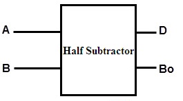
Half Subtractor Block Diagram
There are certain rules followed for this process of subtraction. These rules can be mentioned clearly with the help of the truth table.
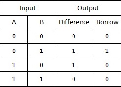
Half Subtractor Truth Table
Explanation of Truth Table
Based on the bits applied at the inputs the values at the outputs in terms of Difference and Borrow are generated.
- If the inputs A and B both are at 0. Their output is generated is also remains at 0.
- If the value of A is o and B is 1. That is A<B. In such cases, the borrow value changes to 1.
- If the value of A=1 and B=0. The Difference value is 1 and the borrow remains unchanged.
- If both the A and B values are the same. This results in the difference and the borrow to be at 0.
So we can summarize that for the values of A greater than or equal to B, the borrow bit remains at 0. In case A bit is less than B the borrow bit is changed to 1. These subtractors can be designed by using logic gate X-OR, NAND, etc…
The Truth Tables are very important in the realizations of the digital circuits. Based on this the Karnaugh Maps are plotted.
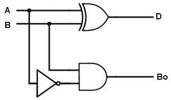
Half Subtractor Circuit
The steps involved in the process of subtraction in the above circuit can be summarized as:
- To generate the value of difference the inputs A and B are applied to the exclusive OR gate.
- The borrow bit can be generated based on the AND gate.
- The input A is complemented with the help of the NOT gate connected to it.
- The complemented value of A is applied to the AND gate.
- Based on these steps the Difference and the Borrow bits are generated.
- The logic utilized for Sum value in the adder will be the same for the Difference value in subtractor.
However, the same operation can be carried out by using NAND gates.
K-Map
To obtain the ‘Boolean Expressions’ for this circuit K-Map technique is used. The truth table is considered and the separate analysis for the difference and the borrow bits is done.
The K-Map for the Difference bit is
Half Subtractor K-map (Difference)
Based on the truth table on focussing the column of difference. The value of 1 is focused on realization and determining the expression. It is a two-bit minimization technique. Basing on the applied inputs for the values of A and B the value of the difference is 1 at 01 and 10.
Hence from the above illustration, the value of the Difference bit is analyzed as
D= A XOR B
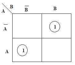
Similarly, the K-Map for the Borrow bit is
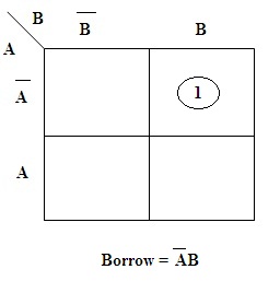
Half Subtractor K-map (Borrow)
In the case, of K-Map for the borrow, the value 1 is present for A=0 and B=1 inputs. Hence the expression for Borrow is generated.
Based on this mapping the obtained equations result in the determination of final values.
Please refer to this link to know more about Logic Gates MCQs
Applications
There are various applications of these subtractors. Practically they are simple to analyze. Some of them are listed as follows.
- To subtract the numbers present in the least position at the columns these subtractors are preferred.
- The Arithmetic and Logic Unit (ALU) present in the processor prefers this unit for subtraction.
- To minimize the distortions in the sound these are used.
- Based on the operation required the half subtractor has the capability of increasing or decreasing the number of operators.
The above are some of the applications that are defined practically.
Please refer to this link to know more about Half Subtractor MCQs & Combinational Logic Circuits MCQs.
Even though the circuit is simple and capable of generating a difference and the borrow bits. These circuits cannot utilize the borrow from the other previous stages. During the real-time performance of these arithmetic operations, these subtractors cannot be preferred. Can you tell how a complement is performed in the circuits using logic gates?