An operational amplifier or Op-Amp is a linear device that is used in ideal DC amplification, signal conditioning, filtering, and also in mathematical operations like addition, subtraction, integration, and differentiation. Op-amp is a voltage amplifying device which is having external feedback components such as capacitors and resistors between output and input terminals. The feedback components presenting in Op-Amp are useful to carry on the operation in an efficient way. An Op-Amp is a three-terminal device that consists of two high impedance inputs i.e. inverting input and non-inverting input and one output port and it can be current or voltage. This op-amp is mainly used for enhancing low signal levels. An op-amp differentiator can be active or passive based on the components used in designing. It is basically a high pass filter and we will use this differentiator amplifier in frequency modulators and wave shaping circuits.
What is an Op-Amp Differentiator?
Definition: An op amp differentiator is a circuit configuration that produces output voltage amplitude which is proportional to the rate of change of input voltage. It means when there is a change in the input voltage signal, then immediately the output voltage will change.
If the differentiator is only having an RC network then it is called a passive differentiator, but if the differentiator is having active circuit components like operational amplifiers and transistors then it is called an active differentiator. This active differentiator has lower output resistance and higher output voltage when compared to passive differentiator or simple RC differentiators.
Normally these op Amps are designed to respond for rectangular and triangular input waveforms. If the input given is the sine wave, then the output will be the cosine wave with a phase shift of 90 degrees. If the input given is a triangular wave, the output that will get generated is a square waveform
Op-Amp Differentiator Circuit
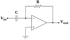
Here we can see the Op-Amp differentiator circuit diagram. This circuit uses a capacitor in series with the input voltage. Capacitor ‘C’ remains uncharged and it acts as an open circuit when the input is given is DC input. The non-inverting terminal is connected to the ground. The output is connected to the inverting input terminal through a feedback resistor R1.
Op Amp Differentiator
Many mathematical operations like addition, subtraction, differentiation, and integration are performed by this operational amplifier differentiator circuit. The output voltage generated by the Op-Amp circuit is proportional to the time derivative input voltage. Due to this, it is called a differentiator and the op Amp circuit also behaves as a voltage follower.
In the above circuit diagram, the node voltage of Op-Amp at the inverting terminal is zero, then the flow of current through capacitor C is
Iin =If
[If = Vout/Rf]
The capacitor charge is equal to the capacitance and the input voltage
Q = CVin
Therefore the change in charge rate is
dQ/dt = CdVin/dt
But the current through the capacitor is equal to dQ/dt
Iin = CdVin/dt =If
-Vout/Rf= CdVin/dt
The operational amplifier differentiator ideal output can be written as
Vout = RfCdVin/dt
As amplitude V is constant, Vout =0
To simplify, Assume C1Rf = 1
But coming to the practical scenario, the output is not zero because the step wave takes time to rise from 0 to Vm volts.
At t= o, the output appears like a spike
When an input is given as a square wave, the output waveform will contain positive and negative spikes implies in the charging and discharging of a capacitor.
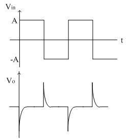
Output Waveforms
Frequency Response of Ideal Differentiator
The gain of the Op-Amp differentiator depends on the frequency of the input signal. When f=0, in DC inputs, the output will become zero. When input signal frequency increases, output also increases.
At frequency f, the differentiator gain becomes unity.
The gain becomes less than unity when the frequency is less than ‘f’
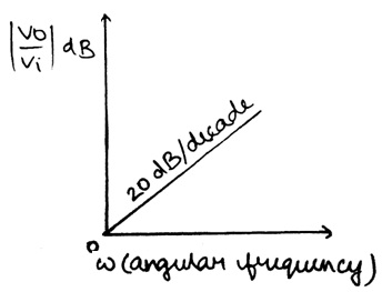
The gain increases at 20dB per decade when the frequency is beyond ‘f’
Practical Op-Amp Differentiator Circuit
In ideal differentiator, when the gain is directly proportional to frequency. So any rise in frequency results in a rise in gain, which results in the Instability of the differentiator at high frequencies, and thus noise arises. Here we can see the circuit diagram of the practical Op-Amp differentiator.
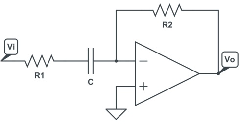
Practical Op-Amp Differentiator Circuit
The problems that are caused can be corrected through this practical circuit which uses R1 in series with C1 and again Cf in parallel with Rf. The practical circuit output voltage can be written as
Vout = RfC1 {d (VIN)/dt}
Here we can see the differentiation between the output voltage and the input voltage is RfC1 times
What happened in this circuit is,
At high frequencies, capacitor Cf and Resistor R1 stabilize the circuit which is useful in reducing the noise of the circuit.
Please refer to this link to know more about Operational Amplifier MCQs
Frequency Response
The frequency response of op-amp differentiator is, as we know the gain is directly proportional to frequency, gain rises with a rise in frequency and gain reaches unity i.e. 0dB at a particular frequency f1. Gain increases at 20dB per decade until input frequency reaches f2. Beyond f2 frequency, the differentiator gain starts decreasing at 20dB per decade.
Frequency Response
This is due to the addition of capacitor Cf and Resistor R1 to the circuit
This figure represents the frequency response curve of a practical Op-Amp differentiator.
Applications
The applications of op-amp differentiators include the following.
- One of the major applications of op-amp differentiator is wave shaping circuits. This can be used in the detection of high-frequency components in the input signal
- These Op-Amp differentiators are normally designed for performing an operation on rectangular and triangular signals.
Thus, this is all about an overview of op-amp differentiator. The mathematical differentiation operation is performed by the op-amp differentiator circuit with respect to time. It means the output voltage is directly proportional to the rate of change of input signal. The op-amp differentiator circuit uses reactive components i.e. usually a capacitor than an inductor, it means op Amp differentiating amplifier is with inverting amplifier circuit configuration.
This circuit commonly operates on rectangular and triangular signals. If this op Amp differentiator starts working on sine wave inputs, they are having some frequency limitations. Here is a question for you, what is an op-amp integrator?