In a world increasingly reliant on sustainable energy, creating your own DIY solar-powered USB charger is not only a great eco-friendly project but also an excellent way to understand basic electronics. Whether you’re an engineering student, hobbyist, or eco-conscious traveler, this project is simple, affordable, and doesn’t require advanced skills. This article provides brief information on a DIY solar USB phone charger step-by-step procedure.
What is a Solar USB Phone Charger?
A Solar USB Charger uses solar energy to generate electricity and charge USB devices like smartphones. It typically involves a solar panel, a voltage regulator, and a USB output module — all powered by the sun.
Components Required
The required components to make this DIY solar USB phone charger include the following.
|
Component |
Specs | Qty | Approx Cost (INR) |
Approx Cost (USD) |
| Solar Panel | 6V, 1W to 3W | 1 | 120–180 | $1.5–$2.5 |
| Lithium-ion Battery | 3.7V, 2200mAh (18650 cell) | 1 | 100 | $1.2 |
| TP4056 Charging Module | With protection | 1 | 35 | $0.5 |
| MT3608 Boost Converter | Boosts 3.7V to 5V | 1 | 50 | $0.6 |
| USB Female Port | Standard Type-A | 1 | 10 | $0.1 |
| Diode | 1N5819 (prevents backflow) | 1 | 5 | $0.05 |
| Switch | SPST | 1 | 10 | $0.1 |
| Enclosure | Small plastic box | 1 | 50–100 | $0.6–$1.2 |
| Wires + Connectors | Jumper cables/solder wires | — | 20 | $0.25 |
| Total Cost | — | — | 400–500 | $5–$6 |
DIY Solar USB Phone Charger Circuit Diagram
The connections of this circuit follow as;
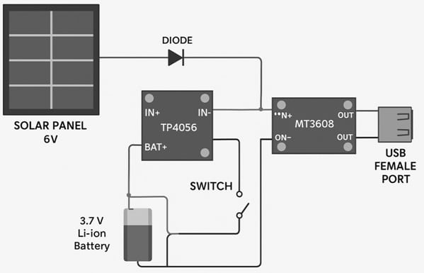
Solar USB Phone Charger Circuit
- Solar Panel → TP4056 input (IN+ / IN−).
- TP4056 output (BAT+ / BAT−) → Battery.
- Battery output → MT3608 input (IN+ / IN−).
- MT3608 output (OUT+ / OUT−) → USB Port.
- Connect the battery to B+ / B- and load to OUT+ / OUT-.
- 1N5819 Diode placed between solar panel +ve and TP4056 IN+ for backflow protection,
TP4056 – Lithium Battery Charging Module
Function: Charges single-cell Li-ion or Li-Po batteries via micro-USB or Type-C input.
Charging Voltage: 4.2V (standard for 1-cell lithium batteries).
Charging Current: Adjustable up to 1A (typically set at 1A).
Protection: Some modules include overcharge, over-discharge, and short-circuit protection (look for ones with DW01 and FS8205 chips).
Use: Common in portable battery chargers, DIY power banks, and solar-powered battery systems.
MT3608 – DC-DC Boost Converter Module
Function: Steps up low DC voltage (e.g., from a 3.7V battery) to a higher voltage (e.g., 5V for USB charging).
Input Voltage: 2V–24V.
Output Voltage: Adjustable up to 28V (5V common for USB).
Output Current: Up to 2A (with proper cooling).
Efficiency: ~85% (depends on input/output conditions)
- Use the onboard potentiometer to set the desired output voltage.
- These two modules together form the heart of compact DIY solar USB chargers: TP4056 handles safe charging, and MT3608 ensures usable 5V output for phones or gadgets.
DIY Solar USB Phone Charger Step-by-Step Instructions
The steps involved in designing DIY solar USB phone charger are discussed below.
Step 1: Connect the Solar Panel to TP4056
Connect the positive terminal of the solar panel to IN+ of TP4056.
Connect the negative terminal to IN−.
Add a diode (1N5819) in series to prevent reverse charging.
Step 2: Connect the Lithium Battery
Solder the battery’s +ve terminal to BAT+ of TP4056.
Solder the -ve terminal to BAT−.
Ensure polarity is correct to avoid damaging the TP4056 module.
Step 3: Connect the MT3608 Boost Converter
From the battery (or BAT+ & BAT−), connect wires to IN+ and IN− of MT3608.
Adjust the potentiometer on MT3608 using a multimeter until you get 5V at the output.
Step 4: Add USB Port
Connect the OUT+ from MT3608 to the +5V pin of the USB port.
Connect OUT to the GND pin.
Step 5: Add On/Off Switch (Optional)
Connect a switch between the MT3608 input and the TP4056 output to turn the charger ON or OFF manually.
Step 6: Enclose the Circuit
Place everything inside a plastic case with proper insulation.
Make holes for the solar panel, USB port, and switch.
Testing the Charger
- Place the solar panel in sunlight.
- Check battery charging LED on TP4056 (red = charging, blue = full).
- Plug in a phone using a USB cable.
- Monitor charging using your phone’s battery screen.
- Charging speed will depend on solar intensity, panel wattage, and battery level.
Performance Tips
- Use a 2W or 3W solar panel for better results.
- Keep the panel angled directly at the sun for maximum exposure.
- You can also charge the battery via the micro-USB input on TP4056 during cloudy days.
Applications
- Emergency phone charging.
- Outdoor camping and trekking.
- Educational STEM projects.
- Sustainable DIY gifts.
Cost Summary:
|
Item |
Estimated Cost (INR) |
Estimated Cost (USD) |
|
Total Project Cost |
400–500 |
$5–$6 |
DIY Solar USB Phone Charger Advantages
- Low cost and eco-friendly.
- Beginner-friendly project.
- Highly portable and customizable.
- Great for school/college exhibitions.
Limitations
- Slow charging in cloudy or shaded environments
- Not suitable for tablets or high-power devices
- Battery protection must be ensured
Conclusion
Building your own DIY solar USB charger is fun, educational, and sustainable. This small device gives you off-grid charging power using clean solar energy — perfect for travelers, students, and DIYers. With just $5–$6, you can create your solar gadget and explore renewable energy hands-on.