In modern audio systems, deep bass plays a crucial role in delivering an immersive listening experience. Whether you are watching movies in a home theatre or enjoying music, low-frequency sound enhances realism and impact. This is where a subwoofer amplifier becomes essential. A subwoofer amplifier is specifically designed to handle low-frequency signals (typically 20 Hz to 200 Hz) and provide sufficient power to drive subwoofers efficiently. Unlike standard audio amplifiers, it focuses on delivering deep, distortion-free bass while maintaining high efficiency. This article provides a complete understanding of subwoofer amplifiers, including their working principle, circuit design, types, wiring methods, and applications.
What is a Subwoofer Amplifier?
A subwoofer amplifier is an electronic amplifier designed to amplify low-frequency audio signals and drive a subwoofer speaker. It performs the following key functions:
- Amplifies weak audio signals
- Filters out high-frequency components
- Delivers high power to low-impedance speakers
- Produces deep and powerful bass output
These amplifiers are widely used in:
- Home theatre systems
- Car audio systems
- Professional sound systems
Subwoofer Frequency Range
Understanding frequency range is important for proper system design.
|
System Type |
Frequency Range |
|
General Subwoofer |
20 Hz – 200 Hz |
| Typical Crossover Range |
80 Hz – 120 Hz |
| THX Standard |
80 Hz |
Frequencies below 20 Hz are called infrasonic, and above 200 Hz are handled by midrange speakers.
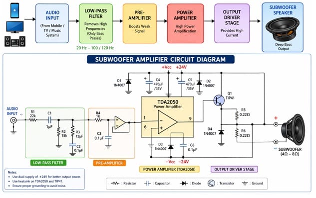
Block Diagram of Subwoofer Amplifier
A typical subwoofer amplifier consists of the following stages:
Audio Input → Low-Pass Filter → Pre-Amplifier → Power Amplifier → Subwoofer.
Subwoofer Amplifier Block Diagram
Stage Explanation
1. Audio Input
Receives signal from source (TV, mobile, receiver)
2. Low-Pass Filter (LPF)
Removes high-frequency signals above cutoff (e.g., 100 Hz)
3. Pre-Amplifier
Boosts signal voltage level
4. Power Amplifier
Increases signal power to drive the speaker
5. Subwoofer Speaker
Converts electrical signal into low-frequency sound waves/
Types of Subwoofer Amplifiers
1. Class A Amplifier
- High sound quality
- Very low efficiency (~25%)
- Generates more heat
2. Class AB Amplifier
- Balanced performance
- Moderate efficiency (~50–70%)
- Common in home audio systems
3. Class D Amplifier (Most Popular)
- Very high efficiency (~90%)
- Low heat generation
Compact size, widely used in modern subwoofer systems
How Does a Subwoofer Amplifier Work?
The working of a subwoofer amplifier can be understood step by step:
1. Signal Input
The audio signal enters the amplifier from the source
2. Filtering Stage
A low-pass filter removes frequencies above the set cutoff (e.g., 100 Hz)
3. Signal Amplification
The filtered signal is amplified in two stages:
- Voltage amplification (preamp)
- Power amplification (output stage)
4. Speaker Driving
The amplified signal drives the subwoofer cone
5. Sound Generation
The cone moves back and forth to produce low-frequency sound waves
Subwoofer Amplifier Circuit (Using TDA2050 IC)
A practical and widely used subwoofer amplifier can be designed using the TDA2050.
Key Components
- TDA2050 IC
- Resistors
- Capacitors
- Power supply (±18V to ±25V)
- Subwoofer speaker (4Ω or 8Ω)
Circuit Stages
1. Low-Pass Filter
- Typically designed using an op-amp or a passive RC network
- Cutoff frequency: ~100 Hz
2. Pre-Amplifier
- Boosts a weak input signal
- Improves signal-to-noise ratio
3. Power Amplifier
TDA2050 provides:
- Output power up to ~32W
- Low distortion
- Thermal protection
Advantages of this Circuit
- Simple design
- Low cost
- Good audio quality
- Suitable for beginners
Important Design Considerations
1. Power Supply
- Stable DC supply required
- Use filtering capacitors to reduce ripple
2. Heat Dissipation
- Use heat sinks for power ICs
- Prevent thermal shutdown
3. Impedance Matching
- Match amplifier output with speaker impedance
- Common values: 4Ω or 8Ω
4. Enclosure Design
- Wooden enclosures improve bass response
- Sealed or ported designs affect sound quality
How to Connect a Subwoofer to an Amplifier
Step-by-Step Connection
1. Connect the amplifier output to the subwoofer terminals
2. Match polarity:
- Positive (+) → Positive (+)
- Negative (−) → Negative (−)
3. Ensure impedance compatibility
4. Adjust crossover frequency
Types of Subwoofers
1. Single Voice Coil (SVC)
- Two terminals
- Simple wiring
2. Dual Voice Coil (DVC)
- Four terminals
- Flexible impedance configurations
Subwoofer Amplifier vs Normal Amplifier
|
Feature |
Subwoofer Amplifier | Normal Amplifier |
|
Frequency Range |
Low (20–200 Hz) | Full range |
|
Purpose |
Bass enhancement |
General audio |
| Filter | Low-pass filter |
Not always present |
| Power Output | High for bass |
Balanced |
Advantages
- Deep and powerful bass
- Improved sound clarity
- Enhanced listening experience
- Efficient low-frequency reproduction
Disadvantages
- Requires proper tuning
- Can consume high power
- Heat generation in high-power designs
Applications of Subwoofer Amplifiers
Subwoofer amplifiers are widely used in:
- Home theatre systems
- Car audio systems
- Cinema halls
- Music studios
- PA (Public Address) systems
They help in:
- Enhancing bass response
- Improving sound depth
- Creating an immersive audio experience
FAQs
1. What is the purpose of a subwoofer amplifier?
It amplifies low-frequency signals to drive subwoofers effectively.
2. What frequency does a subwoofer use?
Typically between 20 Hz and 200 Hz.
3. Which amplifier is best for subwoofers?
Class D amplifiers are widely preferred due to their high efficiency.
4. Can I use a normal amplifier for a subwoofer?
Yes, but performance will not be optimized without a low-pass filter.
5. What is crossover frequency?
It is the frequency at which high frequencies are filtered out (usually ~80–120 Hz).
6. What is impedance in subwoofers?
It is the resistance offered by the speaker, typically 4Ω or 8Ω.
7. Why is a heat sink required?
To dissipate the heat generated by the amplifier.
8. What is the difference between active and passive subwoofers?
- Active: Built-in amplifier
- Passive: Requires an external amplifier
Conclusion
A subwoofer amplifier is a crucial component in any high-quality audio system, designed specifically to deliver deep, powerful, and distortion-free bass. By understanding its working, circuit design, and proper connection techniques, you can significantly improve your audio system performance. With advancements in amplifier technologies—especially Class D amplifiers—modern subwoofer systems are becoming more efficient, compact, and powerful.