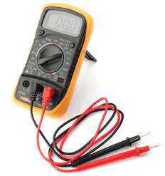
Ohmmeter
While testing, repairing or troubleshooting electronic equipment, you use different meters and different types of test equipment to test proper circuit currents, resistances, voltages and to decide whether the wiring is faulty. Without knowing the operation of the Ohmmeter, it is not possible to connect this instrument to a circuit to test the component. However, to be a competent technician, we need to be competent to do more than merely read a test instrument. For that we need a basic knowledge of how test instruments operate.
It is an electronic device used to measure electrical resistance of a circuit element. Electrical resistance is a measure of how much an object opposes allowing an electrical current to pass through it. Ohmmeters come with different levels of sensitivity. Some Ohmmeters are designed to measure low-resistance materials, and some are used for measuring high-resistance materials. This article discusses the operating principles of an Ohmmeter that you use in equipment’s troubleshooting.
What is an Ohmmeter?
Ohmmeter is an electronic instrument which is widely used to check a complete circuit or to measure the resistance of a circuit element. Micro Ohmmeter, Mega Ohmmeter and Milli- Ohmmeters are used to measure resistance in different applications of electrical testing. A Micro Ohmmeter is used to measure extremely low resistances with high accuracy at particular test currents and is used for bonding contact applications. Micro Ohmmeter fluke is a small portable device, which is used to measure voltage, current and test diodes. This meter has multi selectors to select the desired function, and it automatically ranges to select most measurements. Mega Ohmmeter is used to measure large resistance values. Milli Ohmmeter is used to measure low resistance at high accuracy confirming the value of any electrical circuit.
An Ohmmeter consists of a DC ammeter and few added characteristics:
- A DC source of potential (generally a 3V battery)
- One or more resistors (one of which is variable)
To design an Ohmmeter two types of schemes are used; they are series type Ohmmeter and Shunt type Ohmmeter.
Series Type Ohmmeter
The basic circuit diagram of a series type meter is shown below. In a series type Ohmmeter, the R1 is the current limiting resistor, the Rx is the unknown resistor, the R2 is the zero adjust resistor, the Rm is the internal resistance, E is the internal battery voltage, and A and B are the output terminals of the Ohmmeter.
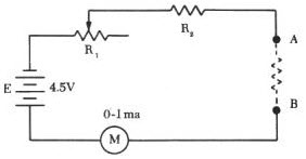
Series Type Ohmmeter
If A&B terminals are connected together the resistors R1 and R2, the battery, the meter form a simple series circuit. The Resistor R2 is adjusted to get full-scale current through the movement, then the Current I=Ifsd. The needle drives back to the maximum position on the scale. So, the current reading on the full scale is marked as 0 Ohms. If A & B terminals are open circuited, no current will flow and the needle will not move. So, the zero current reading on full scale will be marked as infinite to indicate an infinite resistance.
Shunt Type Ohmmeter
The basic circuit diagram of a Shunt type Ohmmeter is shown below. Shunt type Ohmmeter is used to measure small values of resistance. In this type of Ohmmeter, the movement mechanism is connected parallel to the unknown resistance Rx. In this circuit, it is compulsory to use a switch, if not; the current will always flow in the movement mechanism.
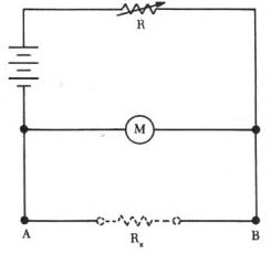
Shunt Type Ohmmeter
When the A and B terminals are closed, then the unknown resistor Rx is short circuited, the needle reads zero because full current flows through the resistor Rx, and I=0 through the meter. Therefore, zero current reading is marked as 0 Ohms.
When the A and B terminals are opened, then the unknown resistor RX is open circuited, no current flows through the RX and full-scale current flows through the meter as the resistor R1 is adjusted. So, maximum current reading is marked ∞ Ohms.
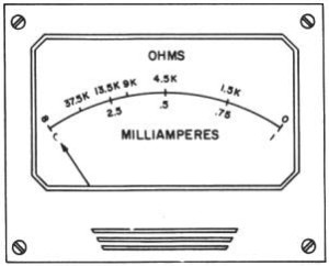
Ohmmeter Scale
Ohmmeter Working
In an Ohmmeter, the deflection of the needle is controlled by the amount of battery current. Before calculating the resistance of an unknown electrical circuit or resistor, first of all, the test leads of the Ohmmeter are shorted together.
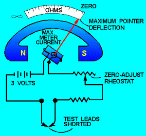
A simple ohmmeter circuit
When the leads are shorted, the meter is adjusted for proper operation on the selected range and the needle drives back to the maximum position on the Ohms scale and the meter current is max. After using an Ohmmeter, the test leads should be removed. If the test leads remain connected to the Ohmmeter, then the battery of the meter gets discharged. When the rheostat is adjusted properly, with the test leads shorted, the needle of the meter comes to zero position, and this specifies a zero resistance between the test leads.
Measuring Circuit Working with an Ohmmeter
When this meter is adjusted for zero reading on the Ohms scale, it is ready for measuring resistance in a circuit. The arrangement of Ohmmeter with a typical circuit is shown below. The power switch of the circuit should always be in the off position. Because the source voltage is applied to the circuit across the meter could damage the meter.
When the test leads of the Ohmmeter are connected serially to the circuit, this causes the current to flow through the circuit being tested. If the meter’s test leads are connected at a point a & b in the circuit, then the amount of the current in the meter coil will depend on the resistance of the meter and the total resistance of the resistors R1&R2. As the meter in the above circuit is pre-adjusted one, the amount of coil movement, therefore, depends exclusively on the resistance of the R1 & R2. The addition of R1 and R2 raises the total series resistance, decreasing the current and therefore decreasing the needle deflection. The needle then comes to rest at a scale for indicating the combined resistance of the R1 and R2.
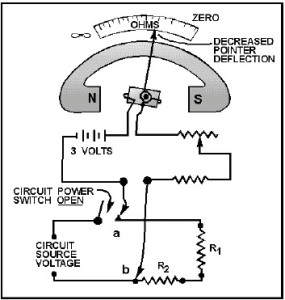
Circuit working with an ohmmeter
If the current limiting resistor R1 or zero adjusts resistor R2 or both are replaced with a larger value resistor, then the current flow and the deflection in the moving coil of the meter will be decreased.
Thus, this article concludes with a brief discussion about the Ohmmeter and its working principle with a circuit diagram which works based on Ohms law principle. For more information regarding the same or phase sequence meters please post your queries by commenting below.
Photo Credits: