Linear Variable Differential Transformer (LVDT) and rotary variable differential transformer (RVDT) is an electrical transformer type sensor used to measure the linear displacement and angular displacement respectively. The circuit diagram and working principle is similar to each other but differentiated in terms of core and shaft movements inside the module. These sensors are also called as electromechanical transducer due to the fact that it yields variable alternating current (AC) output voltage proportional to the changes in induced electromotive force (EMF) in primary and secondary windings. In this article, the LVDT & RVDT introduction is presented. The differences between LVDT & RVDT are explained along with the comparison chart in terms of advantages, applications, and working procedures.
Linear Variable Differential Transformer (LVDT)
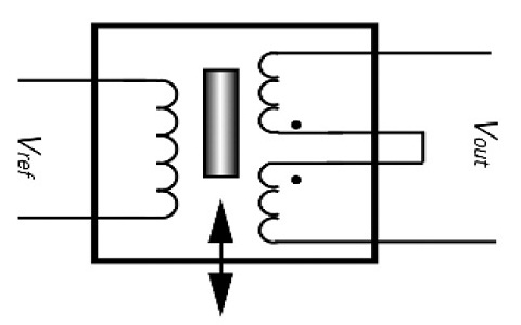
LVDT is an electromechanical sensor used as an external module to measure rectilinear motions. The output is obtained in terms of variable voltage, current, and electrical signals. The design of LVDT is in the form of a cylindrical array with primary winding sandwiched between the two secondary windings. The overall circuit works on the principle of Faraday’s law of electromagnetic induction; when there is any change in the flux linkage results in the induction of EMF across the coil.
The number of turns in LVDT secondary windings is made equal and series-connected to obtain a zero equivalent voltage or equilibrium state during the null position. By doing so, if there is any voltage increase in the first secondary winding results in a voltage drop across the second secondary winding. Thus, the induced equivalent output voltage derives the total displacement variation in the overall system.
Rotary Variable Differential Transformer (RVDT)
Similar to LVDT, RVDT comprises one primary coil, two secondary coils with an equal number of turns, and a movable core. Concerning the working principle, RVDT is an inductive based transducer coil that is used to convert input angular displacement into an electrical signal. A cam-shaped magnetic core, manufactured using soft iron, is placed in between the windings and connected to the shaft.
Even a minute changes in the primary MMF can generate reluctance and magnetic flux that results in the rotation of the camshaft and flow of secondary current at the output stage. Furthermore, the rate of change of magnetic flux is directly proportional to the magnetic flux linkage between the primary and secondary coils.
Comparison chart between LVDT and RVDT
The difference between LVDT & RVDT includes the following.
LVDT and RVDT
| Parameter | LVDT | RVDT |
| Measurement Factor | Linear movements | Angular movements |
| Measurement Range | It is between | Linear over a range of approximately |
| The shape of the core | Rectangular | Cam-shaped |
| Sensitivity | Equivalent to 2.40 mV /V/degree of rotation | Equivalent to 2 to 3 mV /V/degree of rotation |
| Input Voltage | It varies from 1V to 24V at a frequency range of 50Hz | Minimum 3V with a frequency range of 400 Hz to 20KHz |
| Applications | Used to measure weight, pressure, and other product inspection places | Mainly used in controlling units such as fire monitoring, antenna, and radar systems |
The key/main differences between LVDT and RVDT are as follows,
- An LVDT, the cylindrical soft iron core is used to calculate the linear displacement, whereas the cam-shaped rotary ferromagnetic core in RVDT for angular displacement measurements.
- The sensitivity range of LVDT is high, ranging 2.4mV per the voltage and per degree change in moments and 2 to 3 mV per voltage per degree rotation in RVDT.
- The RMS input voltage of LVDT and RVDT is 1-24V and 3V, respectively.
- A phase sensitivity detector connected at the output of LVDT is used to judge and calculate the direction of movement. In RVDT, the angular position is measured by comparing the difference between two output voltage and angular variations.
- The measuring displacement of LVDT and RVDT is +/- 100mm and 40 degrees, respectively.
Advantages of LVDT & RVDT
- In comparison to other measuring instruments, LVDT and RVDT core doesn’t come in contact with the coil, thus reduces the wear and tear and performance degradation in the system.
- These sensors can be used in very rugged conditions such as high-vibration ranges, variant humidity, and wide temperatures.
- Due to its capability to withstand more extensive temperature ranges, it is the most preferred measurement sensor for nuclear power plant applications, marine, military, and aerospace.
- It is used to measure the position variables and obtain feedback insensible control surfaces and deviations in airplane movement and door panel adjustments.
- Furthermore, it can be easily used in both DC and AC operation with simple integration with external signal conditioners.
Even though designing an RVDT and LVDT is simpler in structure, there is a requirement of great effort to measure non-linearity errors, threshold factor, and maximum precision values. Ferromagnetic materials are used to achieve magnetic shielding properties. The bobbin-less coils (free-standing coils) are leveraged to reduce the size of the LVDT gage head and exact coil positions within the model and the nonlinearity difference range should be in the range of 0.15% and 0.35%.
In most of the scenarios, there exists a trade-off between the primary voltage and the secondary impedance due to eddy current loss in the core. To overcome this drawback, the carrier frequency of LVDT and RVDT is approximately set to 2.5-5 kHz and 5-10 kHz respectively.
In general, LVDT and RVDT are used in a wide range of applications and scenarios where there is a requirement of systems with negligible wear and tear properties. Several types of research are carried out in a similar field to determine its advantage using an external source, and the future prospect deals with the utilization of LVDT and RVDT at its utmost level.